UML Summary
What is UML?
- UML (Unified Modeling Language) is basically for visualizing a system design.
- Helpful for documentation.
- Helpful for understanding the structure and behavior of the system.
- UML isn’t a programming language. (visual language or unified modeling language)
- UML has direct relation whit OOP.
What are UML pros?
- Helpful for developers to understand potential errors in programs.
- It is a visual representation and this makes more understandable the relations with classes, entities and etc.
- It is a standard for OOP languages. This provides a common language to describe relationships.
- Well known for most of the developers independent of programming language.
- Easy to plan before codding.
- Increase the readability and re-usability because developers don’t read all of the code. Developers can easily understand the structure from UML and this can prevent duplicating codes.
- They are great free open source tools for creating UMLs.
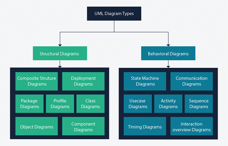
UML Diagram Types
UML Diagrams are classified into two general types.
- Structural Diagrams (static aspects or structure of a system)
- Behavioral Diagrams (dynamic aspects or behavior of the system)

- Class diagrams, sequence diagrams, and use case diagrams are the popular ones.
Structural Diagrams
Deployment Diagram: Depict the physical resources in a system, including nodes, components, and connections. Determines how the software is deployed.

Composite Structure Diagram: provides a logical overview of all or part of a software system at a micro-level. Shows the internal part of a class.

Package Diagram: Organize elements of a system into related groups to minimize dependencies between packages.

Profile Diagram: Diagram that uses stereotypes, tagged values, and constraints to extend and customize UML.

Class Diagram: The backbone of almost every object-oriented method, including UML.
 https://www.visual-paradigm.com/guide/uml-unified-modeling-language/uml-class-diagram-tutorial/
Object Diagram: Describes the static structure of a system at a particular time.
 https://www.visual-paradigm.com/guide/uml-unified-modeling-language/what-is-object-diagram/
Component Diagram: Describes the organization of physical software components, including source code, run-time (binary) code, and executables.

Behavioral Diagrams
Communication Diagram: Emphasizes the messages exchanged between objects in an application.
 https://www.lucidchart.com/pages/uml-communication-diagram
State Machine Diagram: Typically is used to describe state-dependent behavior for an object.
 https://www.visual-paradigm.com/guide/uml-unified-modeling-language/what-is-state-machine-diagram/
Activity Diagram: Activity diagrams are used to model workflow or business processes and internal operations.
 https://www.lucidchart.com/pages/uml-activity-diagram
Sequence Diagram: Describes how, and in what order a group of objects works together. These diagrams are used by software developers and business professionals to understand requirements for a new system or to document an existing process.
 https://www.geeksforgeeks.org/unified-modeling-language-uml-sequence-diagrams/
Usecase Diagram: Use case diagrams are referred to as behavior diagrams used to describe a set of actions that some system or systems should or can perform in collaboration with one or more external users of the system (actors). There is a great article about this.

Timing Diagram: A timing diagram is a specific behavioral modeling diagram that focuses on timing constraints.

The Interaction Overview Diagram: Focuses on the overview of the flow of control of the interactions. The interaction overview diagram is similar to the activity diagram, in that both visualize a sequence of activities.
The difference is that, for an interaction overview, each individual activity is pictured as a frame that can contain a nested interaction diagram.
 https://en.wikipedia.org/wiki/Interaction_overview_diagram
References:


